
High-Level System Architecture
This page presents a birds eye view of our entire system. The basics of how data is actually processed, from initial sensor inputs, to the heart of the operation our compute layer (which runs our driverless software stack), to the output layer where our most ideal control actions are turned into motor commands.
Driverless System Block Diagram
Section titled “Driverless System Block Diagram”

Breakdown
Section titled “Breakdown”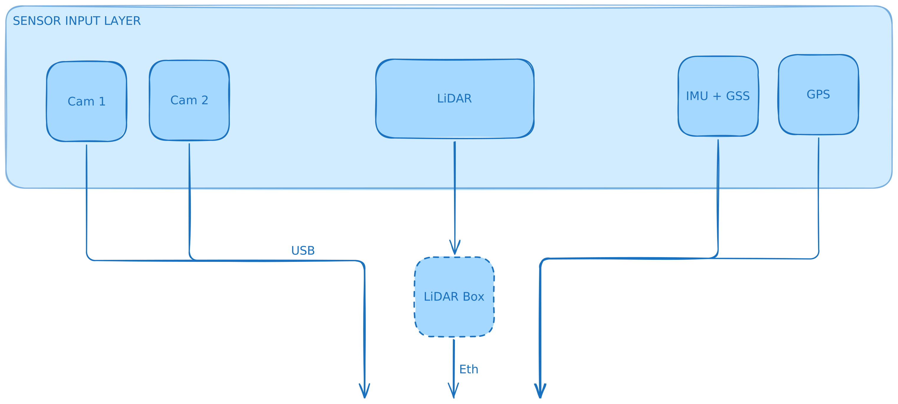 Main inputs:
- LiDAR -> over ethernet through a processing box that preprocesses data in hardware
- Cameras -> over USB to compute
- IMU (Inertial Measurement Unit) -> over CAN
- GPS / GNSS -> over CAN
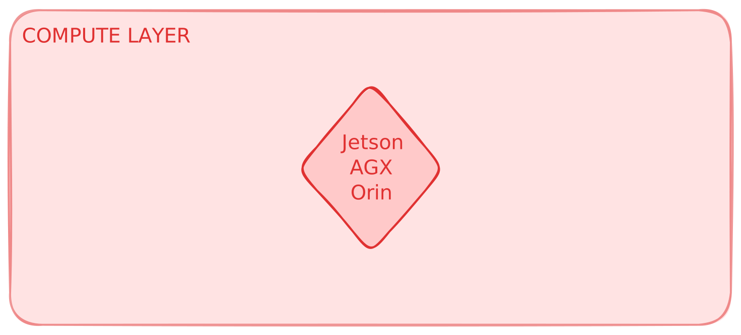
The compute layer is the heart of our operation. We use an NVIDIA Jetson AGX Orin, primarily due to it’s incredible compute power to size ratio.
The compute layer is responsible for running live:
- Sensor data ingestion, configuration, and processing
- Software pipeline, including real-time perceptions, planning, and control
- Heartbeat (safety architecture)
- Data logging
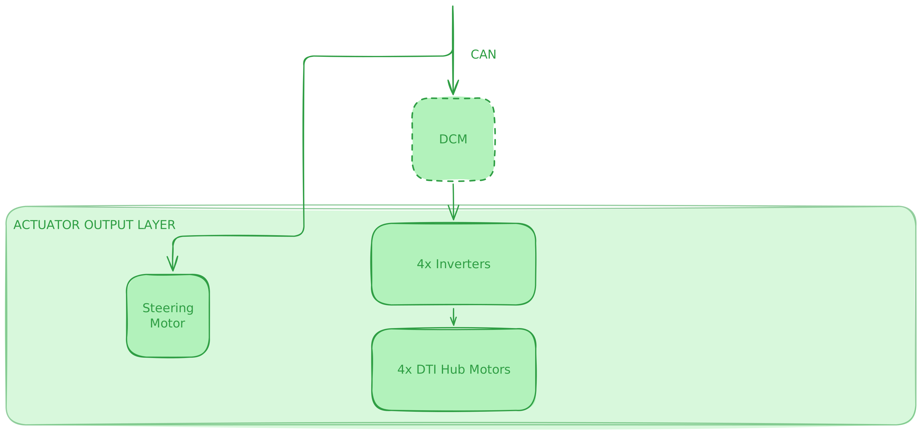
The output layer is the final side of the driverless pipeline. It’s the stage concerned with accurately and quickly taking optimal steering angles and motor torques, and actually actuating them on the vehicle’s hardware.
Our pipeline has two primary methods of actuating the vehicle.
- Direction is determined via a steering motor attached directly to our steering column.
- Speed/acceleration is controlled through our 4 Hub motors that we command via DCM, the Dynamics Controller Module custom PCB designed by energetics to interface cleanly.
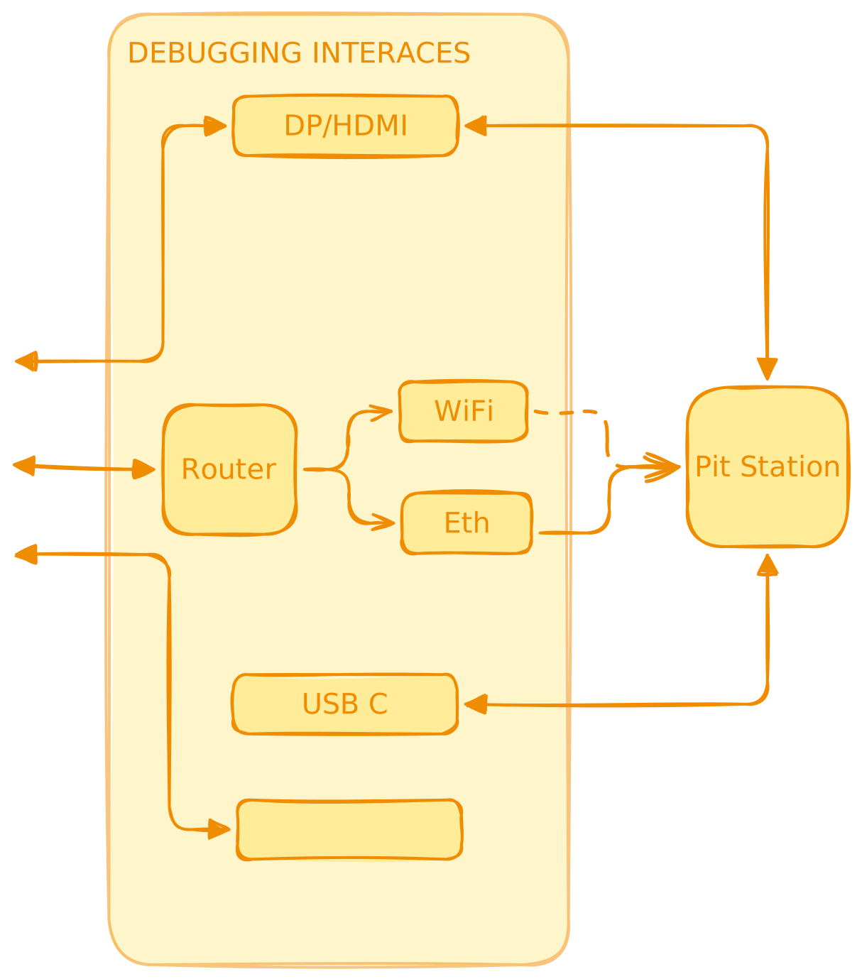
How does data travel from one block to another?
Section titled “How does data travel from one block to another?”- CAN (Controller Area Network) is our main method of communication between the custom PCBs that make up the fabric of our electrical systems. As such, several inputs (IMU, GPS) as well as outputs (motor torque requests) must be sent on CAN.
- Ethernet is unique to driverless, used for our LiDAR as well as connection to our external WiFi/LTE router.
- USB is our 26x-gen camera routing solution
- GMSL (Gigabit Multimedia Serial Link) is our new 27x-gen camera routing solution and allows for real time uncompressed image streams to our compute layer.
- WiFi, accessed through our router, allows for pit devices to interface with the car, updating code, visualizing sensor data live, and setting parameters!